 Byers, J.A. 1983. Electronic fraction collector used for insect sampling
in the photoperiod-induced diel emergence of bark beetles. Physiological Entomology 8:133-138.
Byers, J.A. 1983. Electronic fraction collector used for insect sampling
in the photoperiod-induced diel emergence of bark beetles. Physiological Entomology 8:133-138.  pdf
pdf
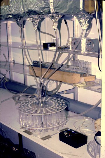
Figure: Fraction collector able to collect emergence from 4 boxes under different photoperiods at constant temperature in a walk-in environmental chamber.
ABSTRACT.
An electronic timer and fraction collector consisting of CMOS
integrated circuits is described. It converts 50- or 60-Hz AC to real-time pulses
in programmable whole-number increments ( 1, I 0 or 60 s) from 3 to 16659,
producing timing periods from 3 s to more than I 1 days. The fraction collector
contains a leaf-switch feedback circuit that automatically adjusts to various
gear motor speeds and sample tube spacings so that proper positioning results.
Hourly collections by the device of the bark beetles Ips typographus L. and
Pityogenes chalcographus L. (Scolytidae) emerging from logs of Norway spruce,
Picea abies, indicated that both species emerged with a diel periodicity. A
unimodal emergence peak for both sexes of both species occurred at midday
in LD 20:4 at a constant 25o C and 80% r.h.
Key words. Fraction collector, sampling, timer, bark beetle, insect emergence,
Ips typographus, Pityogenes chalcographus, Scolytidae, diel periodicity.
Introduction
Fraction collectors are commonly used in
biochemistry and physiology for sequentially
collecting `fractions' of chromatographic
effluents. In principle, they can also be used
in certain behavioural investigations, e.g.
for detecting rhythms of insect emergence
and defecation. They are expensive, however,
costing hundreds of dollars.
Cameron & Borden (1967) using 2-h
manual collections described a diel periodicity
of emergence for the bark beetle Ips paraconfusus Lanier (from California), but they
could not separate the effects of temperature
and photoperiod (or humidity) on the emergence pattern because these parameters were
uncontrolled.
The inexpensive fraction collector and
timer described here was designed in order
to determine the effect of photoperiod on
the emergence of the sexes of Pityogenes chalcographus L. and Ips typographus L. by
automatically collecting the beetles hourly
as they emerged from brood logs of Norway
spruce, Picea abies (L.) Karst, under constant
temperature and humidity. The fraction
collector can be used in any situation where
precisely timed automatic collections in realtime are required, and is inexpensive, reliable,
and relatively simple to build.
Methods and Results
Fraction collector
The schematic circuit of the electronic
timer portion of the fraction collector is
shown in Fig. 1, and the gear motor control
circuit in Fig. 3.
FIG. 1. Schematic circuit of the timer section of the fraction collector (60-Hz AC). The cycle time is
set by (1) the three-position rotary switch at 1, 10 or 60s and by (2) programming IC 5 by means of
DIP switches at the left of the figure as indicated. For example, a cycle time of 631 s is obtained by
setting the rotary switch at the 1 s place and closing the first DIP switch in the `Units' section plus the
first and second switches in the `1Os' section (1 + 2) and the second and third switches in the `100s'
section (2 + 4) to yield 1 + 30 + 600 = 631s. All switches are each connected to ground through a 30k Ohm
resistor as indicated for the last two switches in the `1000s' section. Timing is initiated by first connecting
the Start switch to ground for at least three clock pulses and then opening the switch at the desired
starting time. ICs 1, 2, and 4 have +12 V (DC) applied to pin 14 and ground to pin 7, while IC 3 has
+12 at pin 16 and ground at pin 8. *Pins 8, 9, 12, and 13 of IC 2 are connected to ground. All resistors
are 0.25 W. CMOS integrated circuits should not be inserted into their sockets until all connections
have heen made.
For 50-Hz AC, the circuit
shown in Fig. 2 must be inserted in Fig. 1
instead of that shown for IC 3, IC 1B, IC 4A
and 4B.
FIG. 2. Schematic circuit of the 5O-Hz AC divider
section to be inserted in Fig. 1 (for use in Europe)
instead of the corresponding American (60-Hz)
circuit consisting of IC 3, IC 1B, and IC 4A and B.
The same power connections are used as in Fig. 1;
in addition IC 8 requires +12 V at pin l4 and ground
at pin 7.
These circuits are shown to operate
at 12 V (DC), although any voltage between
5 and 15 V can be used with an appropriate
relay (Fig. 3).
FIG. 3. Schematic circuit of the test-tube position sensor and motor turn-on interval control section
of the fraction collector that will accomodate various gear motors of < 2 rpm. *Pins 7, 12 and 13 of
IC 7 and pin 8 of IC 6 are connected to ground while pin 16 of IC 6 and pin 14 of IC 7 are connected
to +12 V (DC).
In Fig. 3, a normally open leaf-switch
with a roller is used to sense the position of
test-tubes on the fraction collector and so
must be placed as shown in Fig. 4. The npn
transistor, Q1, was a 2N2222 or similar
and the 12-V relay (SPST) must have contracts
rated at 120-220 V. Fig. 4 shows the
general plan for constructing the fraction
collector; many variations are possible, however,
depending on the needs and skill of the
builder.
FIG. 4. Diagram of fraction collector in cross-sectional
side view. Two discs (A and B) are drilled
appropriately around the circumference to hold
test-tubes, separated by two support blocks (C),
and held in place by two rings with set screws (P)
above and below. The test-tube-holding discs are
rotated by an axle (E) in bearing (F) attached to
a stand, and the axle is fitted with the shaft of the
gear motor (G). An adjustable block (H) is attached
to the normally open leaf-switch (I) which detects
the position of test tubes (J), and wires from the
gear motor and leaf-switch (K) connect to the control unit (Fig. 3).
The leaf-switch feedback will accommodate many different collector dimensions
and gear motor speeds. (Gear motors of
2 rpm down to about 0.25 rpm will work;
slower speeds are more appropriate for larger
numbers of tubes and larger discs. For proper
operation it is critical that the distance
between the axle and all test-tubes, i.e. the
radius, is approximately equal, otherwise
the leaf-switch will not function consistently.
Spacing between tubes around the disc
periphery does not have to be precise because
of the feedback circuit.
Bark beetle emergence
P. chalcographus and I. typographus were
obtained from laboratory cultures, maintained on Norway spruce logs, originally
from the province of Všrmland, Sweden.
About seventy-five unsexed P. chalcographus
were allowed to bore freely for 24 h on each
of two spruce logs (28 x 7 cm diam.) on 16
March 1982. A third log (28 x 10 cm diam.)
had thirteen holes drilled through the outer
bark, and each hole had a male I. typographus
inserted. After 24 h, nineteen females were
released, and soon joined the males in their
nuptial chambers.
The logs were then placed inside a clear
plastic emergence box (22 x 16 x 32 cm)
painted first black and then white externally
except for one side `window' (7.5 x 16 cm
high) under which a plastic funnel was placed
beneath a hole in the floor of the box to
collect beetles that were attracted to the
light. A plastic tube from the funnel directed
the beetles to a test-tube in the fraction
collector. A thin film of sebaceous oil around
the top inside wall of the tubes prevented
beetles from escaping. Illumination inside the
box was 2100 lx near the window and < 100
lx at the back.
The emergence box and fraction collector
were placed inside a 12.6-m3 environmental
chamber (Karl Weiss, Giessen, Germany)
which regulated the temperature at 25Ī0.2o C
and humidity at 80Ī5% r.h. Air from the
chamber was drawn through the box with
a suction system at about 11 l/min. The
photoperiod was 20 h light:4 h dark, with the
photophase beginning at 01.00 hours local
time. Beetles were caught hourly by the
fraction collector from 10 to 31 April 1982,
and the mean time of emergence was calculated for each sex.
The emergence of both sexes of I. typographus and P. chalcographus exhibited
unimodal peaks occurring at approximately
midday (Fig. 5). The mean time of emergence
for males and females of I.typographus was
11.28 h local time Ī48 min (Ī95% CI) and
11.58 h Ī47 min, respectively (not significantly different, P > 0.1, t-test).
For male and female P. chalcographus, mean times were
at 10.57 h Ī43 min and 10.48 h Ī 17 min (difference also NS).
FIG. 5. Effect of photoperiod on the time of emergence of Ips typographus
and Pityogenes chalcographus from separate spruce logs contained in the
same plastic emergence box held at constant 25oC
and 80% r.h. (10-31 April 1982). The vertical
bars on each curve designate the mean emergence
time. Points are the result of 3-h rolling averages.
Sample data obtained from the fraction collector.
The sex ratio (male:female) of emergence for
I. typographus during the period 10-31
April was 1:1.35, and did not differ significantly (P > 0.1, chi-square) over the three
successive periods 10-15, 16-22 and 23-31
April. The sex ratio for P. chalcographus was
1:1.18 during the same period, and similarly
did not significantly differ over the three
successive periods. The mean time of emergence for both sexes of both species occurred
approximately at midday on all three successive periods above.
Discussion
Fraction collector operation
The AC sinusoidal waveform from the 110-120V 60-Hz or 220-240V 50-Hz power
outlets is `squared' by ICs 1A, 2A and 2B
to provide a real-time base. These timing
pulses are applied to pin 10 of the binary
counter/divider, IC 3, which can count up to
212 (or 4096) before recycling. Any number
up to 4096 can be obtained by coupling one
or more of the twelve pin outputs representing
20 to 211 to a multi-input AND gate (IC 1B
and IC 4). When all outputs selected go
`high', the AND gate output then goes `high'
and by connecting its output to the reset
of IC 3 (pin 11) the counter is instantly
reset to begin the timing cycle again. For
example, to obtain a 1-s pulse the 60-Hz
is multiplied by 60 (22+23+24+25; pins
6, 5, 3 and 2) as shown in Fig. 1 for IC 1B.
A three-position rotary switch is used to select
the appropriate timing pulse of 1, 10 or 60s.
The brief pulse from the AND gate resets
IC 3 to zero so all its outputs go `low', but
the pulse is long enough to `clock' IC 5 one
count via pin 1. IC 5 is a programmable
divide-by N counter (Jameco Electronics,
Belmont, California) which in Fig. 1 has been
connected in the divide-by-10 mode (other
modes are possible, see COS/MOS Integrated
Circuits 1980, RCA Corp. 688p.) with an
output pulse (at pin 23) equal to one cycle
of the clock-input signal. In other words,
the LED will turn on for 1, 10 or 60s
depending on the rotary switch setting.
The time between LED turn-on is programmed by means of the 16 DIP switches (on-off)
all connected to +12 V and each connected to ground through a 30-k Ohm resistor
and to the respective `jam inputs' (pins
3, 4, 5, 6, etc., as shown in Fig. 1).
Any time period in whole increments between
3 and 16659 multipfied by 1, 10 or 60 s
can be obtained. The `units' section can only
be programmed from I to 9 while the `10s',
`100s' and `1000s' can be programmed from
1 to 15 so the highest programmable number
is 9 + 150 + 1500 + 15000 =16659 (over 11.5
days at the 60-s position). However, a timing
pulse less than three counts cannot be programmed (< 3 s).
The timing period can be initiated when
desired by connecting the Start switch (from
pin 13, IC 5) to ground for at least three
clock pulses (3, 30, or 180 s) and then switching at the appropriate starting time. This
function is important when one wants to have
the fraction collector rotate at a specific
time such as on the hour.
The output pulse from IC 5 is coupled to
the `clock' input of IC 6 (Fig. 3) so that
pin 3 which is `high' now goes `low' and pin 2
goes high and causes the OR gates (doubled
for more output drive) to go high. This biases
the transistor Q1 to conduct DC and turns on
the relay conducting AC to the gear motor
and rotates the fraction collector. As the
test-tube moves away from the leaf-switch
(Fig. 3), the contacts of the switch open in
the gap between tubes causing the other inputs
to the OR gates to go high thus maintaining
power to the motor, but pin 15 of IC 6 also
goes high which resets the IC so that pin 2
now goes low and pin 3 becomes high again
(the initial condition).
The motor continues to turn, however,
until the next test-tube closes the leaf-switch
and a `low' condition at all OR gate inputs
results. The `low' OR gate output then stops
the transistor/relay, and the collector ceases
to rotate until the next timing pulse from the
circuit in Fig. 1. The leaf-switch position
must be adjusted by set screws at `H' in
Fig. 4 to facilitate proper contact with the
test-tubes. The type of gear motor and the
spacing between adjacent test-tubes does
not need to be precisely determined because
of this feedback sensing circuit.
The multiple-output electronic timer designed by Byers (1981) can also be used as
a supplementary timer for the fraction
collector. This is done by connecting the
output of the 4082 AND gate (IC 11A) in
Fig. 1 of Byers (1981) to pin 1 of IC 5 in Fig.
1 here. The four inputs of the AND gate
(IC 11A) must then all be connected to an
output of either IC 7 or IC 8 to obtain pulses
of every 10 min or h, respectively, for deriving
periods of up to 16659 h (over a year) in
whole number increments.
If the fraction collector circuitry is `false
triggered' by spurious high-voltage transients
on the power-line, sometimes caused by inductive motors on the same line, the use of
a power-line filter commonly used for home
computers (R. L. Drake Co., Miamisburg,
Ohio, or similar) allows stable operation.
Bark beetle emergence
The decline in emergence that begins at
midday indicates that the beetles are anticipating the
onset of darkness, since no environmental parameters were changing during this
time (Fig. 5). This is evidence for a light-cycle-induced periodicity of emergence which
may be controlled by a circadian rhythm.
The influence of temperature and other
conditions in nature may alter this basic
pattern, however. For example, flight activity
during the spring `swarming' in Sweden is
often limited to the warmest part of the day,
so emergence peaks in nature may be more
compressed than in Fig. 5.
There was no evidence to indicate that
the sexes of each species emerged differently,
but in I.paraconfusus in California, temperature appears to influence the emergence
of each sex differently (Cameron & Borden,
1967). In this species a unimodal peak emergence for both sexes occurs near the middle
of the day at temperatures below 22o C,
but at intermediate temperatures (22-26o C)
males have a unimodal peak just before
midday while females exhibit a bimodal peak,
one coinciding with the male's and a later
peak in the afternoon (16.00-18.00 hours).
The peaks of emergence of males and
females appeared to diverge at temperatures
above 26oC, with males emerging before noon
and females in the afternoon (but both
avoiding midday high temperatures).
Although light intensity, humidity, and
especially temperature were not controlled,
Cameron & Borden argued that the gradual
decline in emergence during favourable
temperatures which preceded dusk indicated
that the emergence might be under the control
of some other factor, such as response to an
external key (e.g. light intensity) or a circadian rhythm.
They also hypothesized that the bimodal
flight response to pheromone that occurs in
the morning and afternoon (Vitť & Gara,
1962; Gara & Vitť, 1962; Gara, 1963),
apparently temperature dependent, was a
result in part of the emergence patterns.
Furthermore, they stated `the single peak of
flight activity observed by Gara & Vitť
(1962) under cool spring field conditions
could be a reflection of the single emergence
peak' at temperatures below 22oC. However,
this may be over-emphasizing the influence
of emergence on the time of catch on traps
releasing pheromone, since the effect of
temperature and other factors on flight
activity and their ability to respond may be
more significant.
In the case of I. typographus and P. chalcographus, the temperatures favourable for
flight response to pheromone usually occur
during midday and the subsequent few hours
(Annila, 1969), so emergence rhythms have
probably evolved to coincide with this time.
In California, where midday temperatures on
the bark are likely to be lethal, this has
probably selected for beetles which do not
emerge during high temperature (usually
at midday) and which make use of internal
(circadian) timing to avoid emerging near
the end of the light period.
Thus all three species apparently emerge
at the time of day most favourable for survival, when the temperature is optimal for
flight and possibly with sufficient time to
locate breeding areas. They apparently avoid
emerging just before dusk since they would
be forced to spend the night and the next
morning exposed to the risk of predation and
other hazards. Further work is needed to
determine if the diel periodicities observed
are the result of circadian rhythnls.
JOHN A. BYERS
Department of Ecology, Animal Ecology, Lund University, SE-223 62 Lund, Sweden
Present address:

|
|---|
Acknowledgments
This study was made within the `Odour
signals for controlled flight of pest insects'
and funded by the Swedish Research Councils
(NFR, FRN and SJFR).
References
Annila, E,. (1969) Influence of temperature upon
the development and voltinism of Ips typographus L. (Coleoptera, Scolytidae). Annales
Zoologici Fennici, 6, 161-207.
Byers, J.A. (1981) Versatile electronic timer for
synchronous switching of multiple electrical
devices. Behaviour Research Methods and
Instumentation, 13, 381-383.
Cameron, E.A. & Borden, J.H. (1967) Emergence
patterns of Ips confusus (Coleoptera: Scolytidae)
from ponderosa pine. Canadian Entomologist,
99, 236-244.
Gara, R.I. (1963) Studies on the flight behavior
of Ips confusus (LeC.) (Coleoptera: Scolytidae)
in response to attractive material. Contributions
Boyce Thompson Institute, 22, 51-66.
Gara, R.I. & Vitť, J.P. (1962) Studies on the flight
patterns of bark beetles (Coleoptera: Scolytidae)
in second growth ponderosa pine forest. Contributions Boyce Thompson Institute, 21,
275-290.
Vitť, J.Y. & Gara, R.I. (1962) Volatile attractants
from ponderosa pine attacked by bark beetles
(Coleoptera: Scolytidae). Contributions: Boyce
Thompson Institute, 21, 251-274.