 Byers, J.A. and Unkrich, M.A. 1983. Electronic Light Intensity Control to Simulate Dusk and Dawn Conditions.
Ann. Entomol. Soc. Am. 76: 556-558.
Byers, J.A. and Unkrich, M.A. 1983. Electronic Light Intensity Control to Simulate Dusk and Dawn Conditions.
Ann. Entomol. Soc. Am. 76: 556-558.  pdf
pdf
Abstract.
Simulation of sunrise and sunset light conditions is achieved with an electronic light
intensity control using DC- or AC-powered incandescent lamps. The duration of the sunrise and sunset
is easily adjusted and the photoperiod is controlled with a standard 24-h timer. The light intensity
control is especially useful for behavioral studies of crepuscular insects.
 FIG. 1. Light intensity control for DC lamps. List of components -- Resistors, 0.25 watt: (2) 30 K Ohm; Potentiometers: (1) 2 M Ohm;
Capacitor: (1) 2200 µf electrolytic l6 V: Transistors: (one per lamp) npn 2N3055 heat-sinked; Diodes: (3) IN4001; Integrated
Circuit: (1) LM741; Lamps: 6 volt. 6 candlepower: Timer: (1) standard 24-h; Relay: (1) DPST 120 V.
FIG. 1. Light intensity control for DC lamps. List of components -- Resistors, 0.25 watt: (2) 30 K Ohm; Potentiometers: (1) 2 M Ohm;
Capacitor: (1) 2200 µf electrolytic l6 V: Transistors: (one per lamp) npn 2N3055 heat-sinked; Diodes: (3) IN4001; Integrated
Circuit: (1) LM741; Lamps: 6 volt. 6 candlepower: Timer: (1) standard 24-h; Relay: (1) DPST 120 V.
Most studies of the effects of photoperiods on insect
behavior and physiology have utilized instant oN/off light
control (Lipton and Sutherland 1970, Leppla and Spangler 1971,
Ball and Chaudhury 1973, Roberts l974,
Truman 1974, Chabora and Shukis 1979, Leppla et al.
1979). However, simulation of dusk and dawn light intensity
changes may be required to properly observe
insect activity rhythms in the laboratory. Several devices
have been described that gradually change the light intensity
during the circadian period. Unfortunately, the
control systems were mechanically complicated and
consisted of such parts as timing motors (Moody et al.
1973), "light shutters" (Turner et al. 1977a,b), solenoid,
clutch plates and springs (Sparks 1973) or gears,
cams and rubber bands (Eaton l980).
Most environmental chambers use AC current to power
the incandescent and fluorescent lights. Shields (1980)
found that activity levels and turning rates of females of
the minute pirate bug, Orius tristicolor (White), (Hemiptera: Anthocoridae)
were higher under DC powered
incandescent light than under flickering AC light (120
c/sec). Therefore, an electronic device with variable dusk
and dawn dimming periods controlled by a standard 24-h on-off timer is
described that can provide power to
lights with either DC or AC current.
Materials and Methods
The light intensity control device (Fig. 1, above) uses a
standard 24-h timer (or electronic timer, Byers 1981) to
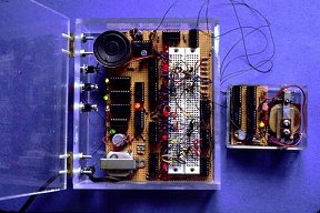
Figure at left: Electronic timer in Byers 1981
actuate a 120 volt DPST relay which either allows
charging or discharging of C, through a 2 M Ohm linear
potentiometer (R1) during the period of light intensity
change. Independent control of the dusk and dawn periods
can be achieved by adding a second 2 M Ohm potentiometer to Fig. 1.
One potentiometer would be connected
to +12 V and the other to ground. The DPST relay
would switch pin 2/C1 to either potentiometer. C1 may
consist of several smaller value capacitors connected in
parallel. The voltage of C1 determines the output voltage
of the 741 op amp (pin 6), which ranges from about 0.5
to 5 volts. The diode in parallel with C1 is used to prevent
pin 6 from going above about 6.7 V. The diodes
between pin 6 and the transistors, or "to Fig 2" (see
Fig. 1) are used to assure that the lamps (DC or AC)
turn off when output becomes low. The diodes can be
any type with a reverse breakdown greater than 15 V
(IN4001, IN4002).
The number of 6-volt DC lamps (6 c.p.) that can be
driven depends on the output current capabilities of the
particular I2-volt power supply. The power transistors,
Q1, (2N3055 or similar) must be heat sinked. If a large
number of 6-volt lamps are needed, the 741 op amp may
not provide enough current to drive the transistors. In
this case, the op amp could drive thc base of a npn
transistor (2N2222 or power) with its emitter (see arrows, Fig. 2)
connected to the bases of all the power
transistors, as in Fig. 1.
Fig. 2. Dimming circuit for AC lamps controlled by light intensity control (Fig. 1 ). List of components --
Resistors, 0.25 watt: (2) 100 Ohm, (1) K Ohm, (1) 4.7 K Ohm, (1) 10 K Ohm, (1) 16 K Ohm, 4 watt, (1) 20 K Ohm, (1) 100 K Ohm;
Potentiometers: (1) 50 K Ohm; Capacitors:
(1) 0.0047 or 0.005 µf, (1) 0.1 µf, 200 V., (1) 470 µf, 16 V: Transistors: Q2,
2N3702, Q3 Sylvania ECG6401,
Q4-5 2N2222, Q6, triac, 10 A, 200-400 V; Diodes: (1) IN4003, red LED, 12 V zener, 1 watt;
Lamps: 120 V, 100 watt;
Photoresistor: CdS. Radio Shack #276-116, 0.5 M Ohm dark.
In Fig. 2, the output of the op amp drives a red LED.
The LED and a CNS photoresistor (Radio Shack #276-116, 0.5 M Ohm resistance in dark)
are wrapped together
with opaque electrical tape to prevent ambient light from
reaching the photoresistor. The light from the LED, adjusted
via the 50 K Ohm potentiometer, that impinges on
the photoresistor effects the unijunction transistor, Q3
(Sylvania ECG6401 ), which varies its firing rate and
causes the triac, Q6 to vary the light intensity of AC
powered lamps. The triac can be any type that is rated
for the voltage and amperage for the requirements of the
particular 120 V lamps. The remainder of the circuit
(Fig. 2) has been modified from Marston ( 1973). Transistor
Q2 can be any low-power pnp type (2N3702) and
transistors Q4 and Q5 can be any low-power npn type
(2N2222). The power transistors (Fig. 1) and the triac(s)
must be heat sinked and separated from the other electrical
components so radiant heat does not affect operation of the control circuits.
Discussion
Thc duration of the "sunrise" and "sunset" period
(delta t in sec). adjusted by the potentiometer R1 is determined
by the following equation: delta t = R1C1 delta V/6 V.
Where R1 is in ohms, C1 in µf, and delta V = Vmax
op amp output minus Vmin op amp output (delta V typically 4.5
volts). The values of R1 and C1 shown in Fig. 1 will
cause this transition period to range from a few seconds
up to about 66 min. The lamps will extinguish at the
end of the dim-off period, however, a second group of
lamps of constant intensity could set the minimum level
of light. The brightness of this second group of lamps
could be regulated by npn power transistors similar to
those in Fig. 1, but instead of their bases connected to
the diode they would be connected through a 100 K Ohm
potentiometer to the positive supply voltagc. Thus, this
would allow insects which may need a certain minimal
amount of light to exhibit normal behavior, as for example
the response of male moths to pheromones (Bartell 1977).
The change in current supplied to the lamps is approximately
linear over the period, although the wavelength of light
emission from incandescent bulbs shifts
toward the infrared as the intensity decreases. However,
the spectrum of natural light similarly shifts toward the
red during sunset and inversely at sunrise due to refraction
of shorter wavelengths.
Generally, we do not believe that AC lamps should
be used in behavioral studies designed to simulate natural
environments because of the possibility that light
flickering may affect the insect. It is well known that
the flicker fusion frequency of diurnal flying insects is
usually above 120 c/sec (Wigglesworth 1972). The control of
DC lamps (Fig. 1) would simulate natural conditions
more closely than AC lamps, providing the voltage
supply, was well filtered with large capacitors (at least
1,000 µf/ampere current, 16 V). However, our AC and
DC circuits provide the experimenter with the option of
comparing the behavioral effects of these two types of
illumination. In any case, the AC circuit would be useful
for control of heaters, motors, and other devices.
The dimmer control circuit is inexpensive to build and
easy to adjust for various dimming periods. The device
should make it practical to study the behavior of many
crepuscular insects.
REFERENCES CITED
Ball, H. J., and M. F. B. Chaudhury. 1973. Photic entrainment
of circadian rhythms by illumination of implanted
brain tissues in the cockroach Blaberus craniifer. J. Insect
Physiol. 19: 823-830.
Bartell, R. J. 1977. Behavioral responses of Lepidoptera to
pheromones. pp. 201-213 In, H. H. Shorey and J. J.
McKelvey, Jr. [eds.], Chemical Control of Insect Behavior.
John Wiley and Sons, New York. 414 pp.
Byers, J. A. 1981. Versatile electronic timer for synchronous
switching of multiple electrical devices. Behav. Res. Methods Instrum. 13: 381-383.
Chabora, P. C., and A. A. Shukis. 1979. The automated
recording of insect activity: The house fly. Ann. Entomol.
Soc. Am. 72: 287-290.
Eaton, J. L. 1980. A simple cam-operated light intensity control.
Ann. Entomol. Soc. Am. 73: 81-82.
Leppla, N. C., and H. G. Spangler. 1971. A flight cage
actograph for recording circadian periodicity of pink bollworm moths.
Ibid. 64: 1431-1434.
Leppla, N. C., E. W. Hamilton, R. H. Guy, and F. L. Lee.
1979. Circadian rhythms of locomotion in six noctuid species.
Ibid. 72: 209-215.
Lipton, G. R., and D. J. Sutherland.1970. Activity rhythms
in the American cockroach Periplaneta americana. J. Insect Physiol. 16: 1555-1556.
Marston, R. M. 1973. 110 thyristor projects using scr's and
triacs. Hayden Book Co., Inc. Rochelle Park, N.J. 138 pp.
Moody, D. S., V. C. Mastro, and T. L. Payne. 1973. Automatic light-dimming system to simulate twilight in en-
vironmental chambers. J. Econ. Entomol. 66: 1334-1335.
Roberts, S. K. 1974. Circadian rhythms in cockroaches. Effects of optic
lobe lesions. J. Comp. Physiol. 88: 2I-30.
Shields, E. J. 1980. Locomotory pctivity of Orius tristicolor
under various intensities of flickering and non-flickering
light. Ann. Entomol. Soc. Am. 73: 74-77.
Sparks, M. R. 1973. An automatic light-intensity control for
insect studies. J. Econ. Entomol. 66: 988-989.
Tanabe, A. M. 1974. An automated lighting cycle for the
insectary. Ibid. 67: 305-307.
Truman, J. W. 1974. Physiology of insect rhythms IV. Role
of the brain in the regulation of the flight rhythm of the
giant silkmoths. J. Comp. Physiol. 95: 281-296.
Turner, W. K., N. C. Leppla, V. Chew, and F. L. Lee.
1977a. Light quality influences on carbon dioxide output
and mating of cabbage looper mothes. Ann. Entomol. Soc.
Am. 70: 259-263.
Turner, W. K., N. C. Leppla, R. H. Guy, and F. L. Lee.
1977b. Method for continuously monitoring the CO2 output
of caged insects: Potential application in quality control of
colonized insects. USDA, ARS-S-166. 5 pp.
Wigglesworth, V. B. 1972. The Principles of Insect Physiology,
p. 239. 7th Ed. John Wiley and Sons, Inc., New York.
827 pp.
JOHN A. BYERS* and MARK A. UNKRICH
Department of Entomological Sciences,
University, of Califomia, Berkeley, California 94720
*Present address:

|
|---|